Fotobooth
Code voor Arduino (1ste versie)
#include <Keyboard.h>

const int inputPin = 12; // Pin connected to Nayax output
int lastState = LOW;     // Previous state of the input pin
int count;

void setup() {
  pinMode(inputPin, INPUT);         // Set the pin as input
  digitalWrite(LED_BUILTIN, HIGH);  // initialize digital pin LED_BUILTIN as an output.
  pinMode(LED_BUILTIN, OUTPUT);     // turn the LED on (HIGH is the voltage level)
  Keyboard.begin();                 // Initialize the keyboard emulation
  Serial.begin(9600);
  count = 0;
  delay(5000);                       // Delay to give time to connect the Arduino
  digitalWrite(LED_BUILTIN, LOW);    // turn the LED off by making the voltage LOW
}

void loop() {

  int currentState = digitalRead(inputPin);  // Read the Nayax signal

  // Check if the state has changed from LOW to HIGH
  if (currentState == HIGH && lastState == LOW) {
    count++;
    Serial.print("Pulse: ");
    Serial.println(count);
    digitalWrite(LED_BUILTIN, HIGH);   // turn the LED on (HIGH is the voltage level)
    Keyboard.press(0x20);              // press space
    delay(100);
    Keyboard.releaseAll();             // Release the key
    delay(1000);                        // Debounce delay to prevent multiple triggers
    digitalWrite(LED_BUILTIN, LOW);    // turn the LED off by making the voltage LOW
  }

  lastState = currentState;  // Update the last state
}
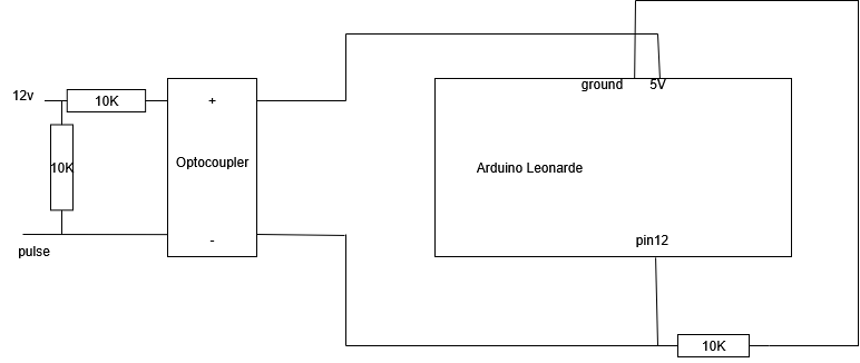
Aansluitschema

Arduino 5v - Optocoupler +
Arduino GRND - weerstand 10K - pin12
Arduino Pin 12 - GRND Optocoupler
Optocoupler primair 12 volt via 10K weerstand
Pin 12 wordt met een pull down weerstand laag (0) gehouden. De (1) is 5V wordt via de optocoupler verbonden aan pin12 als er een signaal via de optocoupler binnenkomt. De stroom die door de 10K weerstand loopt als de optocoupler 'aan' staat, is 0.5 mA (2.5 mW).
De 10K weerstand voor de 12v primaire kant v/d optocoupler is proefondervindelijk vastgesteld. Bij 12v en 10K weerstand staat er 5v op de primare ingang en werkt de optocoupler goed. Meer spanning (lager weerstand kan) volgens de specs maar is onnodig.
Explanation primary side optocoupler
Since the pulse goes low (0V) when active and you want the LED to turn on, we need to connect the pulse wire to the cathode (Pin 2) and supply a positive voltage to the anode (Pin 1) through a current-limiting resistor. When the pulse pulls low, it completes the circuit, allowing current to flow through the LED. When floating, a pull-up resistor ensures the LED stays off.
Primary (Input) Side: Connecting to Nayax
- Calculate the Current-Limiting Resistor:
- LED forward voltage (V_F): ~1.4V.
- Desired LED current (I_F): 10mA (0.01A).
- Voltage drop across the resistor: 24V - 1.4V = 22.6V.
- Resistor value: R = 22.6V / 0.01A = 2260Ω → Use a 2.2kΩ resistor.
- Add a Pull-Up Resistor:
- When the pulse wire floats (inactive), we need the LED off. A pull-up resistor on the cathode (Pin 2) to +24V ensures no current flows when the wire is floating.
- Use a 10kΩ pull-up resistor. This keeps the cathode at 24V when floating, preventing current through the LED.
- Wiring the Primary Side:
- +24V Supply: Connect to one end of the 2.2kΩ resistor.
- 2.2kΩ Resistor to Pin 1 (Anode): Connect the other end to Pin 1 of the PC817.
- Pin 2 (Cathode): Connect to the green Pulse 1 wire and one end of the 10kΩ pull-up resistor.
- 10kΩ Pull-Up Resistor: Connect the other end to +24V.
- Nayax Ground: Ensure the 24V supply ground is the same as the Nayax ground.
- Behavior:
- Inactive (Floating): The 10kΩ pull-up keeps Pin 2 at 24V, same as Pin 1’s effective voltage (24V - 1.4V drop across resistor), so no current flows (LED off).
- Active (Low, 0V): The pulse wire pulls Pin 2 to ground, creating a 22.6V drop across the resistor and LED, driving ~10mA through the LED (on).
Explanation of Behavior
- Inactive (Floating): The pull-up resistor ties Pin 2 to 24V. Pin 1 is at ~22.6V (24V minus the resistor drop if any current flowed), but since Pin 2 is also at 24V, there’s no voltage difference across the LED—no current, no light.
- Active (Low, 0V): The Nayax pulls the green wire (Pin 2) to ground. Now, Pin 1 is at 24V through the resistor, and Pin 2 is at 0V. The LED sees ~1.4V, the resistor drops the remaining 22.6V, and ~10mA flows—LED turns on.
New code (v2) to ignore small pulses
#include <Keyboard.h>

const int inputPin = 12; // Pin connected to Nayax output
int lastState = LOW;
int count;
unsigned long lastPulseTime = 0;
const unsigned long debounceDelay = 1000; // Minimum time between pulses (ms)
const unsigned long pulseValidationTime = 10; // Must stay HIGH at least this long (ms)

void setup() {
  pinMode(inputPin, INPUT);
  pinMode(LED_BUILTIN, OUTPUT);
  digitalWrite(LED_BUILTIN, HIGH);
  Keyboard.begin();
  Serial.begin(9600);
  count = 0;
  delay(5000);
  digitalWrite(LED_BUILTIN, LOW);
}

void loop() {
  int currentState = digitalRead(inputPin);

  if (currentState == HIGH && lastState == LOW) {
    // Wait a bit to check if the signal is stable
    delay(pulseValidationTime);
    if (digitalRead(inputPin) == HIGH) {
      unsigned long now = millis();
      if (now - lastPulseTime > debounceDelay) {
        count++;
        Serial.print("Pulse: ");
        Serial.println(count);
        digitalWrite(LED_BUILTIN, HIGH);
        Keyboard.press(0x20);
        delay(100);
        Keyboard.releaseAll();
        digitalWrite(LED_BUILTIN, LOW);
        lastPulseTime = now;
      }
    }
  }

  lastState = currentState;
}
