
PageESP32-WROOM-32S 32d
Full name
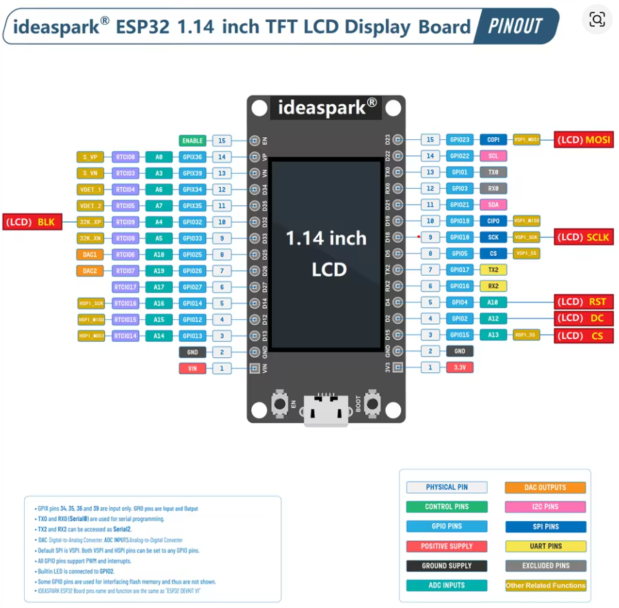
IdealSpark® ESP32 Development Board Integrated 2.9 cm ST7789 135x240 TFT LCD Display, WiFi+BL Wireless Module, CH340 Driver USB Type-C for Arduino Micropython
Board description
The Dual Core 30pin ESP32-WROOM-32S 32d is compatible with the Arduino IDE. To get started, you'll need to install the ESP32 board definitions through the Arduino Board Manager. Here’s how:
-
Install the Board Package:
In the Arduino IDE, open File > Preferences and add the following URL to the “Additional Boards Manager URLs” field:https://dl.espressif.com/dl/package_esp32_index.json -
Use the Board Manager:
Go to Tools > Board > Boards Manager, search for “ESP32,” and install the package provided by Espressif. -
Select Your Board:
Once installed, select the appropriate ESP32 board from Tools > Board. Your Dual Core ESP32-WROOM-32S should appear in the list, allowing you to program it using the familiar Arduino environment.
With these steps, you can leverage the Arduino IDE to develop and upload code to your ESP32 board.
Modulenaam in Arduino IDE: ESP32 Dev Module
                      ┌──────────────────────────────────┐
                      │   Ideaspark® ESP32 1.14" LCD     │
                      │        TFT Display Board          │
                      │                                  │
Left Side             │                                  │            Right Side
──────────────────────┤                                  ├──────────────────────────────
(15)  EN        ─────▶│ EN / Enable                      │◀──── GPIO23  VSPI_MOSI   (LCD MOSI)
(14)  GPIO36     ─────▶│ A0 / RTCIO08                    │◀──── GPIO22  SCL         (I2C Clock)
(13)  GPIO39     ─────▶│ A3 / RTCIO03                    │◀──── GPIO1   TX0         (USB Serial TX)
(12)  GPIO34     ─────▶│ A6 / RTCIO04                    │◀──── GPIO3   RX0         (USB Serial RX)
(11)  GPIO35     ─────▶│ A7 / RTCIO05                    │◀──── GPIO21  SDA         (I2C Data / LCD BLK)
(10)  GPIO32     ─────▶│ A4 / RTCIO09                    │◀──── GPIO19  VSPI_MISO   (SPI MISO)
 (9)  GPIO33     ─────▶│ A5 / RTCIO08                    │◀──── GPIO18  VSPI_SCK    (LCD SCLK)
 (8)  GPIO25     ─────▶│ DAC1 / RTCIO06                  │◀──── GPIO5   VSPI_SS     (SPI CS)
 (7)  GPIO26     ─────▶│ DAC2 / RTCIO07                  │◀──── GPIO17  TX2         (UART2 TX)
 (6)  GPIO27     ─────▶│ GPIO / RTCIO17                  │◀──── GPIO16  RX2         (UART2 RX)
 (5)  GPIO14     ─────▶│ HSPI_SCK / RTCIO16              │◀──── GPIO4   A10         (LCD RST)
 (4)  GPIO12     ─────▶│ HSPI_MISO / RTCIO15             │◀──── GPIO2   A12         (LCD DC)
 (3)  GPIO13     ─────▶│ HSPI_MOSI / RTCIO14             │◀──── GPIO15  A13         (LCD CS)
 (2)  GND        ─────▶│ Ground                          │◀──── GND     —           Ground
 (1)  VIN        ─────▶│ Power In (5V)                   │◀──── 3.3V    —           Power Out (3.3V)
──────────────────────┤                                  ├──────────────────────────────
                      │          USB-C Port              │
                      └──────────────────────────────────┘
Graphic LIbrary
https://learn.adafruit.com/adafruit-gfx-graphics-library?view=all
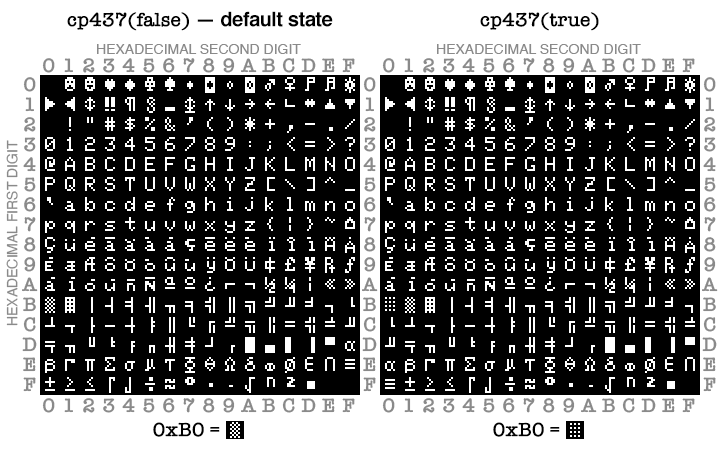
Char Set
Deep Sleep wake op PIR (ANY_HIGH)
#include <esp_sleep.h>

#define PIR_PIN 13  // RTC-capable pin

void setup() {
  pinMode(PIR_PIN, INPUT);            // of INPUT_PULLDOWN als je die wilt gebruiken
  // Wake bij HIGH op deze pin (EXT1, multiple pins mogelijk)
  esp_sleep_enable_ext1_wakeup(1ULL << PIR_PIN, ESP_EXT1_WAKEUP_ANY_HIGH);

  // ... event. nog iets loggen

  esp_deep_sleep_start();
}

void loop() {}
Light Sleep wake op PIR
#include <esp_sleep.h>

#define PIR_PIN 13

void setup() {
  Serial.begin(115200);
  pinMode(PIR_PIN, INPUT);
  esp_sleep_enable_ext1_wakeup(1ULL << PIR_PIN, ESP_EXT1_WAKEUP_ANY_HIGH);
}

void loop() {
  // Doe je werk...
  delay(50);

  // Ga naar light sleep tot PIR HIGH wordt
  esp_light_sleep_start();

  // Wakker! (PIR hield de lijn even hoog; verwerk event)
  Serial.println("Motion detected (woke from light sleep)");
  // kleine debounce
  delay(200);
}